Partical Count Test
Viable Particle Count:-
ISO has made classifications for clean-room as it mentioned in the ISO guidelines ISO 14644-1 . As per that classification Particle count in clean room are achieved as per classification of the area.
ISO has defined 9 class standards for classification of clean rooms. In every class has it's fixed defined limit for different sizes of particle.
Particle count test done in two condition at REST and at OPERATION.
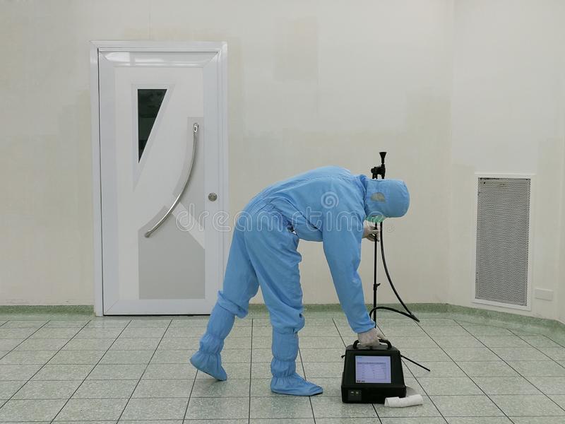
For particle counting particle counter Machine is used which gives the printed record of particle present in the area.This particle count test done at 4 to 5 location in one room and varies depending on the area of room.
Length of tubing used for partial counter machine should not be more than 1 meter.
Rest condition:-
In this condition test done in a cleanroom which is not having any production activity or not any person inside the cleanroom who's doing some work.
Running Condition:-
In this condition partical count test done while cleanroom is in running condition.
Number of sampling Points for particle Count:-
The number of sampling points in the area where particle Count should taken, is now not been calculated as per formula of square root of the surface area.
In 2015 ISO has released the new updated version of ISO 14644-1. In that version this major changes done for particle Count test.
Now the Particle Count test Sampling location taken from the ISO standard sampling location chart given below.
Sampling point locations can be followed as mentioned in the below table, for the large clean rooms or clean zones can be derived by equation as mentioned in the below table.
Set up the particle counter in cleanroom or clean zone where the particle count to be measured as described in the layout. The sampling locations are evenly distributed throughout the cleanroom or clean zone.
The Sampling probe shall be positioned in the airflow at a distance of 1 to 1.5 meter from the filter or at working level and start to take readings.If the calculation results only one sample location, then consider minimum of three sample points for testing of particle count.Record the results of each sample measurement.Sampling locations related to cleanroom area as mentioned in the below table.
Area of cleanroom (m2) less than or equal to | Minimum number of sampling locations to be tested (NL) |
2 | 1 |
4 | 2 |
6 | 3 |
8 | 4 |
10 | 5 |
24 | 6 |
28 | 7 |
32 | 8 |
36 | 9 |
52 | 10 |
56 | 11 |
64 | 12 |
68 | 13 |
72 | 14 |
76 | 15 |
104 | 16 |
108 | 17 |
116 | 18 |
148 | 19 |
156 | 20 |
192 | 21 |
232 | 22 |
276 | 23 |
352 | 24 |
436 | 25 |
636 | 26 |
1000 | 27 |
> 1000 | Mentioned below Formula in the note |
Considering area falls between two values in the table, the greater of the two should be selected.In the case of unidirectional airflow, the area may be considered as the cross section of the moving air perpendicular to the direction of the airflow. In all other cases the area may be considered as the horizontal plan area of the cleanroom or clean zone.
Sampling location for large clean rooms or clean zones below formula will be applicable. NL = 27 x [A/1000]
NL is the minimum number of sampling locations to be evaluated, rounded up to the next whole number.
A is the area of the cleanroom in m².
Pre-Requisite:
Tests covered in preceding sections for Air Velocity Measurement and Air Change Rate Calculation and HEPA Filter Integrity Test should be completed and results should comply with respective acceptance criteria.
Method Applied:
1. Set the Particulate Counter for following parameters
Sampling Volume : 0.05 Cubic Meter
Mode : Auto
Cycles : 1
Run Time : 1 minute
Delay Time : 1 min
Print : All Samples
2. Particulate counting shall be carried out at predefined locations.

Comments
Post a Comment